The earler post is here: Mini Moto / Pocket Bike Exhaust Port Mods .
Port matching, which consists of reshaping port outlets to be size and shape matched for better flow, is all but standard practice in all forms of motorsport and is often done at home by enthusiasts who are looking to extract all the performance possible from their engines.
Mini motos / pocket bikes are almost always tuned to varying degrees and indeed, the internet is full of articles and websites dedicated towards helping you make your moto faster. There are many articles which point towards 'opening up' the exhaust port on these bikes, but for all the time and effort being put into opening them up, there's almost always a huge port mismatch between the cylinder head and the exhaust pipe.
As I showed in the initial post, this is the typical 'view' the exhaust has as it exits the cylinder head towards the exhaust pipe:
 |
| Head To Pipe Exhaust Port Mismatch |
There's much more detail, along with a couple of crude flow models in the initial post, however as I'd touched upon when writing that, it's not only the area in red here, representing the inlet to the racing exhaust which is the problem, it's the turbulence caused by the exhaust being deflected around this mismatch that has a much greater impact than what is illustrated. Obviously any more 'opening up' of the exhaust port on the head is going to exacerbate this effect instead of serving to resolve it, meaning that another solution was due.
I've also touched upon in the initial post the options of welding the port up and re-machining it to a shape which would match up better to the pipe, or even of possibly using JBWeld as has been suggested. (Note: do NOT use JBWeld to rehape your exhaust port - it will quickly break down under those conditions and you'll have much larger problems than just port mismatch)
The ideal to all of the above would be something which could be bolted on in just a few minutes, requiring an absolute minimum of prep to either of the mating surfaces and ideally requiring no welding or machining whilst offering great flow improvements.
Following on now to the CAD and flow models of the original post, here are some images of a test-fit piece which I've machined from wood. There's a slightly more revised version I've now prototyped in bronze and have working in practice /being tested, but I'd prefer to keep that version under wraps until its' for sale. To the naked eye, there's not much difference at all between that one and this, but there are subtle refinements which manage to extract another couple of CFM of flow.
Finally, after that lengthly introduction, here's the wood model of the 'FlangeFlow' port adapter.
 |
| Wood Prototype FlangeFlow Port Adapter |
I've done a few of these from hardwood as they were quite quick to knock out on the CNC and yet were rigid enough to survive being mocked up and flow tested on several head/pipe combinations.
Unfortunately the available equipment for the flow testing was less than ideal and was rather 'mad scientist / high school science fair' in appearance, but the purpose was served and we were able to reaffirm that the slight changes we were making were in the right direction. We do have formal flow-testing scheduled for the near future.
How much of a difference do the FlangeFlow adapters make? In simulations, >15% was common to see, in the real world, we'll be backing all this up with some extended dyno testing in the near future, but I can tell you this for the moment: You can hear the difference, certainly feel the difference in acceleration/top speed, and it required stepping up one jet size on one 'stage 2' motor, and two jet sizes on a 'stage 3' motor to maintain the air/fuel ratio. Both the motors tested were 49cc air cooled (the initial target platform for these adapters), and both had been initially built with off-the-shelf available components which were then race prepped and the rotating assembly carefully balanced.
The 3x test riders (two very accomplished racers and one amateur) all indicated they felt a 'big improvement' in midrange and especially top end. Acceleration out of corners was improved and straightline speed increased so that one rider commented on having to 'hit the brakes a little earlier to scrub off more speed' before the corner.
These are a couple of images showing the FlowFlange situated against a couple of different cylinder heads and against 2x different race pipes. Note that all the misalignment is addressed and that although kept to under 6mm thick so as not to cause exhaust fitment issues, the flow transition from one shape to the other is radically improved.
 |
| FlangeFlow / Port View 1 |
On these two heads (by different manufacturers with different markings, having had only the ports smoothed but not hogged out, you can clearly see how linearly the FlangeFlow mates to the port shape for a seamless, uninterrupted exhaust flow.
Also, in the reverse direction, with the exhaust pulse pushing the extra air/fuel back from the pipe into the head to be burned, there's a much improved flowpath. This contributes to better cylinder filling, higher cylinder pressures, and more power all the way through the RPM range.
 |
| FlangeFlow / Port View 2 |
Additionally, these pictures show the FlowFlange positioned against a typical race pipe. As indicated in the previous post, of the several exhaust I had access to, all had an inlet diameter within 1mm or so of each other. I've matched the exhaust side up to the proper racing pipes but matching to more mainstream aftermarket pipes is also excellent.
 |
| Exhaust Pipe Match View 1 |
Again, the clear, uninterrupted flow path can clearly be seen as it's presented to the exhaust flow from the head into the pipe.
 |
| Exhaust Pipe Match View 2 |
Though not specifically related to the workings or benefits of the FlowFlange itself,
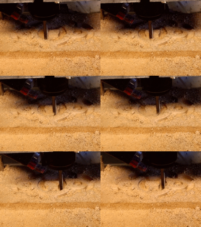
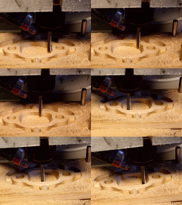
Below are several images of the FlowFlange wood model as it was being cut on the CNC machine.
 |
| Beginning of first top side CNC cut |
 |
| 1/3 of of the first top side cut done |
 |
| Approaching full depth now |
 |
| External profile CNC machinig |
 |
| CNC shaping the internal port contour |
 |
| A bit more port clean up |
 |
| Perimeter milling |
 |
| Milling away the fixture supports |
The FlowFlange is 100% designed, manufactured, and packaged in the UK.
enquiries can be sent to me or to info@mgdesignlondon.com
I am interested in buying a few of these if you still make them or have any left over.
ReplyDelete